 Congratulations On Your Successful Submission
 Submission Failure
The Ground (GND) in electronic circuits plays a crucial role as a reference point for voltage measurements, circuit completion, and safety. Originating in the 19th century with the use of telegraph systems, GND has evolved to encompass various types such as Analog Ground (AGND), Digital Ground (DGND), Power Ground (PGND), and more. Understanding the history, types, and significance of GND is essential for effective circuit design and operation.
What is GND
GND is the abbreviated term for the ground connection of an electrical wire, representing the ground or zero line. So what does GND stand for? It stands for “Ground”. This "ground" is not a true ground in the literal sense; it is assumed for application purposes as a reference point. In the context of power supply, it serves as the negative pole of the power source.
History of GND
The concept of grounding (GND) in electrical systems originated in the early 19th century with the discovery that the ground could serve as a return path for telegraph signals. German scientist Carl August von Steinheil implemented this on an in-service telegraph in 1836–1837. However, issues arose, such as high resistance in the ground connection during dry weather.
In the late 19th century, as telephony replaced telegraphy, interference from induced currents in the earth became a problem. This led to the reintroduction of the two-wire or 'metallic circuit' system around 1883 to address interference and ensure reliable communication.
Why Do You Need a GND
Ground (GND) is indispensable in electronic circuits for several critical reasons:
- Voltage Reference: GND establishes a stable reference point for measuring voltages in the circuit.
- Circuit Completion: Provides the return path for electric current, allowing circuits to operate.
- Safety and Equipment Protection: Ensures a safe path for excess current, preventing electric shocks and protecting equipment.
- Signal Integrity: Minimizes noise and interference, ensuring reliable signal transmission.
- Electromagnetic Compatibility (EMC): Mitigates electromagnetic interference, shielding sensitive components.
- Voltage Stability: Stabilizes voltage levels, preventing unwanted fluctuations.
- Common Reference: Serves as a common reference point for various components within a system.
- System Stability: Contributes to overall stability and reliability of the electrical system.
In essence, grounding is essential for the proper functioning, safety, and stability of electronic circuits. It establishes a reference, completes circuits, protects equipment, and contributes to the overall performance and reliability of electronic systems.
6 Difference Types of GND
#1 Analog Ground (AGND):
Analog ground, or AGND, finds its primary application in analog circuit components, including Analog-to-Digital Converter (ADC) circuits for analog sensors and operational amplification proportional circuits. Due to the delicate nature of analog signals, susceptible to interference from high currents in neighboring circuits, AGND is crucial. Failure to separate AGND may lead to significant voltage drops, distorting analog signals and potentially compromising the functionality of analog circuits.
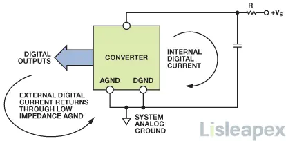
#2 Digital Ground (DGND):
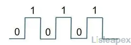
Digital ground, DGND, serves the purpose of grounding digital circuits such as key detection, USB communication, and microcontroller circuits. Digital circuits, characterized by discrete signals of "0" and "1," undergo voltage changes during transitions. To mitigate Electromagnetic Compatibility (EMC) radiation, a distinct DGND is established to effectively isolate digital circuits and minimize their impact on neighboring components.
#3 Power Ground (PGND):
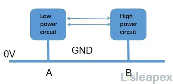
In high-power circuits like motor drives and solenoid valve drives, a separate reference ground called power ground (PGND) is essential. These circuits, characterized by substantial currents, pose a risk of ground offsets between circuits with distinct functions. PGND helps prevent ground shifts that could alter reference voltages, ensuring the stability of the entire circuit.
#4 Power Supply Ground (GND):
Analog ground (AGND), digital ground (DGND), and power ground (PGND) collectively converge as DC ground (GND). Serving as the common 0V reference ground for the entire circuit, the power supply ground is vital. All circuits derive their necessary voltage and current from the power supply, necessitating the unification of various grounds with the power supply ground for seamless circuit operation.
#5 AC Ground (CGND):
AC ground (CGND) is integral in circuit projects involving both AC and DC power, such as AC to DC power supply circuits. This bifurcation into AC and DC sections mandates separate grounding. The AC ground serves as the 0V reference point for the AC segment, while the DC ground serves the same purpose for the DC segment. Engineers often connect AC ground to DC ground using coupling capacitors or inductors to maintain a unified ground (GND) in the overall circuit.
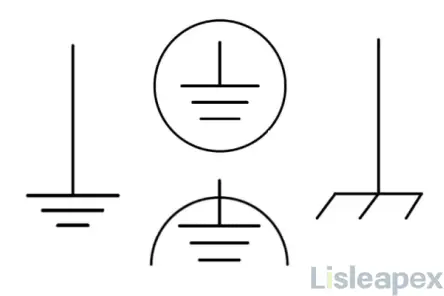
#6 Earth Ground (EGND):
Ensuring human safety, especially in high-voltage and high-current projects exceeding 36V, involves the implementation of earth ground (EGND). Commonly applied in household appliances like electric fans, refrigerators, and televisions, EGND provides an additional safety layer. Engineers connect EGND to the circuit, enhancing safety measures and preventing potential harm to individuals. The integration of EGND is exemplified in sockets designed with earth ground protection.
Differences between Types of GND
This table summarizes the key differences in purpose, concerns, and focus for each type of ground in electronic circuits.
|
Type of Ground |
Purpose |
Concerns |
Key Focus |
|
Analog Ground (AGND) |
Used in analog circuits |
Prevents interference from high currents in neighboring circuits |
Ensures accuracy and integrity of analog signals |
|
Digital Ground (DGND) |
Grounds digital circuits |
Minimizes EMC radiation during transitions between digital "0" and "1" states |
Isolates digital circuits to avoid interference |
|
Power Ground (PGND) |
Used in high-power circuits |
Addresses the risk of ground offsets between circuits with different functions |
Maintains stability and prevents shifts in reference voltages |
|
Power Supply Ground (GND) |
Common 0V reference ground |
Ensures all circuits receive necessary voltage and current from the power supply |
Unifies Analog Ground, Digital Ground, and Power Ground |
|
AC Ground (CGND) |
Part of circuits with both AC and DC power |
Separates AC and DC sections to prevent interference |
Maintains separate grounds for AC and DC components |
|
Earth Ground (EGND) |
Enhances safety in high-voltage projects |
Mitigates potential harm to individuals by providing a safe path for excess currents to the ground |
Acts as a safety measure, especially in household appliances |
Working Principle of GND
The Ground, often denoted as GND, serves as a reference point in electronic circuits. Its working principle is rooted in creating a stable voltage reference against which other voltages in the circuit are measured. Here are the key aspects of the working principle of GND:
Reference Voltage: GND provides a stable and consistent reference voltage point, typically considered as 0 volts. All other voltage measurements in the circuit are referenced against this point.
Voltage Potential: GND serves as a common point of zero voltage potential in the circuit. Voltages are measured with respect to this reference, allowing for a standardized point of comparison.
Completing the Circuit: GND is crucial for completing the electrical circuit. In many circuits, current flows from the power source, through the components, and returns to the power source through the ground. This completes the circuit loop.
Grounding Electrical Charges: GND helps in grounding excess electrical charges, providing a path for current to flow into the Earth. This is particularly important for safety, as it prevents the buildup of static electricity and ensures a safe discharge path.
Common Reference for Components: GND provides a common reference point for all components in a circuit. This common reference simplifies circuit analysis and design, as voltages are measured with respect to the same baseline.
Shielding and Noise Reduction: GND can act as a shield against electromagnetic interference (EMI) and radio-frequency interference (RFI). By properly designing the ground system, unwanted noise and interference can be minimized, ensuring the integrity of signals.
Separation of Circuits: Different types of grounds, such as Analog Ground (AGND), Digital Ground (DGND), and Power Ground (PGND), may be used to separate different functions within a circuit. This segregation helps in preventing interference between circuits and maintaining signal integrity.
Safety: GND plays a crucial role in ensuring the safety of electronic devices and users. Grounding helps prevent electrical shocks and provides a safe path for excess current to dissipate in the event of a fault.
In summary, the working principle of GND involves providing a stable reference voltage, completing electrical circuits, grounding excess charges, serving as a common reference for components, reducing interference, and ensuring safety in electronic systems. The proper design and implementation of the ground system are essential for the reliable and safe operation of electronic circuits.
Common GND In-Circuit Errors
Misconnection of Power between GND and Positive Terminal:
- Description: Newcomers often mistakenly connect power between the GND and positive (+) terminals in a three-end DC energy source.
- Consequence: This error prevents the current from returning to the electrical supply, resulting in a lack of electricity flow through the circuit.
- Corrective Action: The correct power connection involves linking power between the negative (-) and positive (+) terminals to ensure proper current flow.
Neglecting the Earth Ground Connection:
- Description: Some beginners may overlook the significance of connecting the ground terminal to the earth through the three-prong socket.
- Consequence: Omitting the earth ground connection can compromise safety and may lead to improper functioning of the circuit.
- Corrective Action: Emphasize the importance of connecting the ground terminal to the earth for safety and optimal circuit performance.
Failure to Differentiate Between Positive and Negative Terminals:
- Description: Inexperienced individuals may struggle to distinguish between the positive (+) and negative (-) terminals.
- Consequence: Incorrect terminal connection can result in reversed polarity, potentially damaging components and affecting circuit operation.
- Corrective Action: Clearly educate newcomers on terminal distinctions and emphasize the correct orientation for positive and negative connections.
Incomplete Grounding to Chassis:
- Description: Some beginners might overlook the physical attachment of the ground terminal to the chassis.
- Consequence: Inadequate grounding to the chassis can impact the effectiveness of the ground connection, leading to potential issues in the circuit.
- Corrective Action: Stress the importance of physically attaching the ground terminal to the chassis for a robust grounding connection.
These errors highlight common misconceptions and oversights that newcomers may encounter when dealing with a three-end DC energy source and emphasize the corrective actions to ensure proper circuit operation.
Is GND Positive or Negative?
In electronic circuits, the terms positive and negative primarily denote the polarity of voltage, not ground. Ground itself is neither inherently positive nor negative; instead, it serves as a reference point. In direct current (DC) circuits, voltage is described as the potential difference between two points. The point at a higher potential is labeled positive, while the one at a lower potential is labeled negative.
However, ground is not universally considered as having a fixed potential of zero volts or a specific polarity in circuit design. Its role is to act as a reference for measuring voltage. In various electrical systems, ground serves as a reference point against which voltage is measured. For instance, if a voltage source is connected between the circuit and ground, the voltage is deemed positive if it surpasses the ground potential and negative if it falls below it.
It's essential to note that in alternating current (AC) systems, the terms positive and negative are less commonly used since voltage continuously changes polarity. In AC systems, the reference point is often a neutral conductor, and voltage is expressed in terms of phase. Therefore, ground is crucial for establishing a consistent reference for voltage measurements in diverse electrical systems.
What is GND in a Circuit(For Beginner)
GND, or ground, in a circuit refers to the interconnected network of multiple signal lines serving as a reference point for voltage measurements. The specific signals connected to the ground network depend on the characteristics of the circuit.
The functions of GND include:
- Impedance Matching: GND acts as a multi-ground network, addressing signal crosstalk issues arising from impedance mismatches in ground lines.
- Simplified Wiring: Introducing multiple GND networks in a system simplifies the overall wiring layout.
- Interference Reduction: GND networks ensure that various signals remain isolated, minimizing mutual interference and enhancing overall system performance.
- Signal Separation in PCB Layout: During PCB layout, GND networks aid in separating signals, preventing coupling and improving signal integrity.
In a complete circuit, the interconnection of signal lines, ground, and power supply forms a circuit loop with impedance influenced by both power and signal impedances. Mismatched impedances in this loop, particularly during high voltage or current scenarios, can lead to significant signal interference.
Practical circuits recognize the shielding effect of ground on signal lines, but this shielding is absent for power supplies. Consequently, a resistive ground can induce interference currents, emphasizing the importance of designing ground lines to avoid impedance mismatches.
GND networks provide a solution to signal interference by creating a multi-ground system. Care must be taken when implementing multiple GND networks:
Customize ground and GND networks based on specific signal and circuit requirements for each system.
Ensure matching parameters for all grounding and GND networks to maintain proper system operation.
Avoid mixing multiple signals in the same ground network to prevent coupling interference.
Optimize the ground plane area to minimize its impact on other signals.
Prevent parallel connections between ground and signal lines.
When parallel connections are necessary, introduce resistors on each ground line to match impedances.
In PCB design, the layout of GND networks must be strategic, maintaining appropriate distances between signals and ensuring impedance matching. This approach safeguards the performance of the entire system even if one wire is disconnected.
To prevent electromagnetic interference, the introduction of GND networks in systems is crucial. Utilizing multiple GND networks reduces noise signals' impact on the system, enhancing overall performance. In summary, GND networks play a vital role in addressing signal interference, improving system stability, and finding widespread application in diverse circuit scenarios.
How to Choose a Suitable GND?
Choosing the appropriate GND in circuit design involves several key considerations. Firstly, circuit segmentation into distinct functional blocks with independent GNDs is recommended. Employing a layered approach to GND design ensures a clear and organized physical and electrical layout of the circuit board, minimizing potential interferences. Prioritizing the creation of the shortest possible pathways for GND lines helps reduce resistance and inductance in the current loop, enhancing signal integrity.
Adhering to the single-point grounding principle by establishing a primary reference point in the circuit aids in lowering GND loop resistance and streamlining signal return paths. Avoiding the introduction of reflow in GND pathways is crucial to ensure a clear unidirectional flow of current. Selecting GND line capacities based on current requirements is essential, with wider lines recommended for high-power sections to decrease resistance.
Considering electromagnetic compatibility (EMC) is paramount, involving the use of separated GND lines and shielding techniques to diminish electromagnetic radiation and enhance circuit immunity to interference. Referring to circuit design manuals, standards, and literature is vital to ensure GND design aligns with industry specifications and best practices. Finally, validating GND design through simulation tools and real-world testing guarantees circuit stability and performance under diverse operational conditions. These detailed steps ensure the selection and design of a GND that best suits the specific requirements of the circuit.
Conclusion
In conclusion, the Ground (GND) is an indispensable element in electronic circuits, providing stability, safety, and functionality. From its historical roots in telegraphy to its modern applications in diverse circuit types, GND serves as a reference point, completes circuits, and mitigates interference. Choosing the right type of GND and implementing proper grounding techniques are critical for achieving reliable and efficient electronic systems. Whether it's Analog Ground for precision, Digital Ground for isolating digital circuits, or Earth Ground for safety, a well-designed GND system ensures the optimal performance and longevity of electronic circuits.
FAQ
-
Can I use the Earth Ground as a current return path?
Earth Ground is primarily used for safety and is not intended as a current return path. In circuits, the current return path is typically through the conductors in the circuit.
-
Can I connect multiple Grounds together?
Yes, multiple grounds can be connected together, but it's crucial to do so at a single point to avoid ground loops, which can introduce noise and interference.
-
What is the difference between Signal Ground and Power Ground?
Signal Ground is often used for low-level analog or digital signals, while Power Ground is associated with the power supply and higher current paths. It's common to have separate grounds to prevent interference.
-
Is Ground always at zero volts?
In theory, Ground is considered to be at zero volts. However, in a real-world circuit, there may be small voltage differences due to resistance and impedance in the conductors.
Stay updated with Lisleapex by signing up for the newsletter