 Congratulations On Your Successful Submission
 Submission Failure
BJTs and JFETs are pivotal components in semiconductor-based electronic circuits, each offering distinct functionalities and characteristics. While BJTs rely on the movement of charge carriers across junctions, JFETs are governed by voltage variations to control current flow through a channel. Understanding their differences is crucial for optimizing circuit design and performance.
What is BJT (Bipolar Junction Transistor)
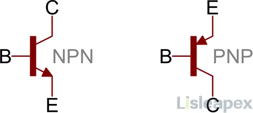
A Bipolar Junction Transistor (BJT) is a fundamental semiconductor device widely utilized in electronics for signal amplification, switching, and current regulation. Comprising three semiconductor layers doped with either P-type or N-type materials arranged in NPN or PNP configurations, the BJT facilitates control over the flow of charge carriers (electrons or holes) between its three terminals: emitter, base, and collector.
By modulating the current flowing between the collector and emitter terminals via the base terminal, BJTs play a crucial role in regulating current flow and signal processing. Their versatility allows for a broad spectrum of applications, including audio amplifiers, digital logic circuits, and power regulation systems.
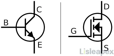
Symbolically represented as either NPN or PNP configurations, BJTs offer impressive current handling capabilities and low output resistance, making them indispensable components in signal amplification and power regulation tasks. With applications ranging from simple radio frequency amplifiers to advanced artificial intelligence processors, BJTs are integral to modern electronic systems across various industries.
What is JFET(Junction Field-Effect Transistor)
A Junction Field-Effect Transistor (JFET) is a semiconductor device widely utilized in electronic circuits for tasks such as signal amplification, impedance matching, and switching. Unlike Bipolar Junction Transistors (BJTs), JFETs are unipolar devices, meaning they operate solely on either electrons or holes, depending on the type of semiconductor material used.
JFETs come in two main configurations: N-channel and P-channel, each utilizing a single type of semiconducting material (either N-type or P-type). The core component of a JFET is the semiconductor channel between the source and drain terminals, whose current flow is controlled by the voltage applied to the gate terminal.
In N-channel JFETs, a negative gate voltage widens the channel, allowing for higher current flow, while in P-channel JFETs, a positive gate voltage achieves the same effect. Known for their high input impedance, low noise characteristics, and simplicity of design, JFETs find applications in amplifiers, voltage-controlled resistors, and analog switches.
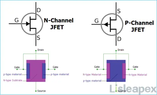
Symbolically represented as N-channel and P-channel configurations, JFETs are essential components in electronic circuits requiring precise control over current flow and signal processing. Their voltage-controlled operation distinguishes them from BJTs and makes them suitable for various high-impedance and low-noise applications across multiple industries.
Comparison: Difference between BJT and JFET
|
Comparison Criteria |
Junction Field-Effect Transistor (JFET) |
Bipolar Junction Transistor (BJT) |
|
Operational Principle |
JFET is a voltage-controlled device, utilizing an electric field to regulate current flow. |
BJT functions as a current-controlled device, utilizing a small current to regulate a larger current flow. |
|
Charge Carriers |
Utilizes only one type of charge carrier (electrons for N-JFET and holes for P-JFET). |
Utilizes both electron and hole charge carriers. |
|
Input Impedance |
JFET exhibits higher input impedance, reducing power draw from preceding stages. |
BJT demonstrates lower input impedance, potentially drawing more power from preceding stages. |
|
Noise |
JFET typically exhibits lower noise levels, making it more suitable for sensitive signal amplification. |
BJT generally produces higher noise levels compared to JFET, though still acceptable for most applications. |
|
Switching Speed |
JFET tends to have lower switching speeds, potentially limiting its use in high-frequency applications. |
BJT boasts higher switching speeds, making it more suitable for high-frequency applications. |
|
Gain |
JFET generally demonstrates lower gain compared to BJTs, potentially limiting its use in power amplification. |
BJT often exhibits higher gain, making it preferable for power amplification applications. |
|
Power Consumption |
JFET typically consumes less power than BJTs, which can be advantageous in power-sensitive applications. |
BJT tends to consume more power compared to JFET, potentially limiting its use in power-sensitive designs. |
|
Complexity of Fabrication |
JFET fabrication is more complex and costlier, resulting in a higher cost per unit. |
BJT fabrication is easier and more cost-effective, leading to a lower overall cost. |
|
Thermal Stability |
JFET is generally more thermally stable than BJTs, providing enhanced reliability in varying temperature conditions. |
BJTs, on the other hand, are less thermally stable compared to JFETs. |
|
Application Fields |
JFET is ideal for signal amplification in sensitive instruments due to its low noise level and high input impedance. |
BJT is more suitable for applications requiring high gain and high-frequency operation, such as in audio amplifiers and digital circuits. |
By comparing BJT and JFET we can know, JFET often outperform BJTs in aspects like input impedance, noise level, and power consumption, making them ideal for certain applications. However, BJTs excel in switching speed and gain, proving their worth in other specific applications. Thus, the choice between JFETs and BJTs largely depends on the particular needs of the application.
JFET vs BJT: Operation
Bipolar Junction Transistor (BJT):
A Bipolar Junction Transistor (BJT) is a three-terminal semiconductor device that relies on the movement of current carriers (electrons and holes) within its three layers – the emitter, base, and collector. There are two types of BJTs: NPN and PNP, distinguished by the arrangement of their layers. In an NPN configuration, current flows from the emitter to the collector when a small control current or voltage is applied to the base terminal. Conversely, in a PNP configuration, current flows in the opposite direction, from the collector to the emitter, when the base terminal receives a positive voltage.
Junction Field-Effect Transistor (JFET):
The Junction Field-Effect Transistor (JFET) is a three-terminal semiconductor device that controls the flow of charge carriers through a channel via an electric field. JFETs come in N-channel and P-channel configurations, depending on the type of semiconductor material used. When a voltage is applied to the gate terminal, an electric field is created, which either enhances or inhibits the flow of charge carriers (electrons or holes) between the source and drain terminals through the channel. JFET operation includes cut-off mode, saturation mode, and pinch-off, where the device's conductivity is modulated based on the applied gate voltage.
In summary, while BJTs rely on current control for operation, JFETs utilize voltage control to regulate the flow of charge carriers through their respective channels.
JFET vs BJT: Noise Performance
The following is the comparison of noise performance between bipolar junction transistors (BJT) and field-effect transistors (FET), particularly under different operating conditions.
Noise Types: BJTs exhibit both thermal and shot noise, while FETs primarily display thermal noise.
Impact of Source Resistance: BJTs tend to have lower noise at low source resistance, while FETs may excel at high source resistance.
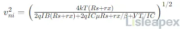
Numerical Analysis: Formulas are provided to calculate noise levels for both types of transistors, with numerical examples illustrating their performance at different source resistances.
BJT Noise Formula for Constant Collector Bias Current (IC = 1 mA)
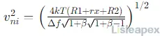
BJT Noise Formula for Optimum Collector Bias Current (IC(opt))
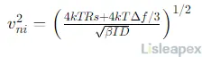
JFET Noise Formula for Constant Drain Bias Current (ID = 1 mA)
BJTs typically offer superior noise performance at low source resistances, while FETs may be preferable for high source resistance due to their capability for zero gate current, reducing noise associated with coupling capacitors and offset current sources.
In summary, the noise performance of BJTs and FETs varies depending on the operating conditions, necessitating careful consideration of circuit requirements for optimal transistor selection.
JFET vs BJT: Pros and Cons
Junction Field-Effect Transistors (JFETs) and Bipolar Junction Transistors (BJTs) are two fundamental components in electronic circuits, each offering distinct Pros and Cons.
Pros of JFETs:
- High Input Impedance: JFETs boast a notably high input impedance, making them ideal for applications requiring a high impedance input signal.
- Low Noise: Compared to BJTs, JFETs exhibit lower noise levels, making them preferable for high-fidelity audio applications where noise reduction is paramount.
- Low Power Consumption: JFETs typically consume less power, making them energy-efficient and suitable for battery-powered devices.
- Simple Biasing: JFETs require simpler biasing arrangements than BJTs, reducing the number of external components needed for functionality and simplifying circuit design.
- Linear Operation: JFETs operate in a linear region, making them suitable for analog applications such as source-controlled resistors.
Cons of JFETs:
- Limited Voltage Gain: JFETs generally have lower voltage gain compared to BJTs, potentially necessitating additional amplification stages in certain scenarios.
- Slow Switching Speeds: While JFETs have comparable switching speeds, they may not be suitable for high-frequency applications due to slower switching times.
- Sensitivity to Overvoltage: JFETs are susceptible to damage if powered above their specified voltage ratings, necessitating strict usage of protection measures to prevent damage.
- Limited Voltage Ratings: JFETs may have lower voltage ratings compared to some BJTs, limiting their applications in certain high-power scenarios.
- Variability: Critical parameters of JFETs can vary significantly between individual devices, requiring careful selection and matching for precise tasks.
Pros of BJTs:
- Amplification: BJTs provide significant amplification capabilities, making them essential for a wide range of electronic tasks and applications.
- Fast Switching Speeds: BJTs offer fast switching responses, making them suitable for high-frequency applications and rapid signal processing.
- Robustness: BJTs are generally more resistant to environmental factors such as temperature changes, enhancing their durability and reliability in various operating conditions.
- Versatility: BJTs find extensive use in both analog and digital technologies, offering designers flexibility and versatility in circuit design and implementation.
- Lower Input Impedance: In scenarios requiring lower input impedance, BJTs excel, providing optimal performance for specific applications.
Cons of BJTs:
- Temperature Sensitivity: BJTs are sensitive to temperature variations, which can degrade performance and necessitate temperature compensation measures.
- Higher Noise Levels: BJTs exhibit higher noise levels compared to JFETs, making them less suitable for applications prioritizing noise reduction.
- Complex Biasing: BJTs may require more complex biasing arrangements than JFETs, introducing additional complexity and potential points of failure in circuit design.
- Power Consumption: BJTs typically consume more power than JFETs, which may not be desirable in power-efficient designs or battery-powered devices.
- Lower Input Impedance: BJTs generally have poorer input impedance compared to JFETs, limiting their applicability in scenarios requiring high input impedance.
JFET vs BJT: Application
BJTs are widely used in amplifiers, switching circuits, power supplies, oscillators, and audio systems, offering fast switching speeds and robust performance. JFETs, on the other hand, excel in applications requiring high input impedance, low noise, and low power consumption, making them ideal for high-fidelity audio amplifiers, voltage-controlled resistors, analog switches, low-noise amplifiers, and battery-operated devices.
Here are details,
Applications of BJTs:
- Amplifiers: BJTs are extensively used in audio and radio amplifier systems to amplify signals for various applications.
- Switching Circuits: They serve as switches in digital circuits, allowing or blocking the flow of current from the collector to the emitter terminal based on the input signal.
- Power Supply: BJTs are employed in power supply circuits for voltage regulation and signal amplification.
- Oscillators: They play a crucial role in oscillator circuits, generating periodic waveforms for various electronic devices.
- Audio Systems: BJTs are commonly utilized in audio systems for tasks such as first-stage amplification and power amplification, contributing to high-fidelity sound reproduction.
Applications of JFETs:
- High-Input Impedance Amplifiers: JFETs, with their high input impedance, are preferred for applications where high input impedance is crucial, such as in high-fidelity audio amplifiers.
- Voltage-Controlled Resistors: They can be integrated into circuits to control parameters or variables using a power source.
- Analog Switches: JFETs serve as analog switches, allowing or blocking the passage of signals based on the applied voltage, making them suitable for various analog applications.
- Low-Noise Amplifiers: JFETs are preferred in applications where signal quality is critical due to their low noise levels, ensuring minimal signal distortion.
- Battery-Operated Devices: With their low power consumption, JFETs are suitable for use in battery-powered electronic devices, contributing to extended battery life and efficient operation.
Which is better: How to Choose between BJT and JFET
When choosing between Bipolar Junction Transistors (BJTs) and Junction Field-Effect Transistors (JFETs), it's essential to consider factors as below,
- Control mechanism: BJT - current-controlled, JFET - voltage-controlled.
- Input impedance: JFET typically has higher input impedance.
- Noise: JFET generally has lower noise levels.
- Power consumption: JFET often consumes less power.
- Speed: BJT usually has faster switching speeds.
- Gain: BJT often offers higher voltage gain.
- Cost and availability: Consider the cost and availability of both types.
- Thermal stability: JFET is typically more thermally stable.
- Application specifics: Evaluate specific requirements and constraints of the application.
Conclusion
The choice between BJT and JFET hinges on various factors such as power requirements, frequency response, cost considerations, and specific application needs. While JFETs often excel in input impedance, noise levels, and power efficiency, BJTs offer advantages in switching speed and gain. Ultimately, the optimal selection depends on balancing these factors to meet the requirements of the intended application.
Related Post:
BJT vs FET: Difference between BJT and FET
Difference Between UJT and BJT Transistor 2024
FAQ
-
Which one is more commonly used in audio amplifier circuits, BJT, or JFET?
Both BJTs and JFETs are used in audio amplifier circuits, but JFETs are often preferred for their lower noise characteristics and higher input impedance.
-
Which one is more suitable for high-frequency applications, BJT, or JFET?
BJTs are often preferred for high-frequency applications due to their higher transconductance and faster switching speeds compared to JFETs.
-
Are BJTs or JFETs more susceptible to temperature variations?
JFETs are generally more stable over temperature variations compared to BJTs, as their characteristics are primarily determined by physical dimensions rather than doping concentrations.
-
How do BJTs and JFETs amplify signals differently?
BJTs amplify signals using both majority and minority charge carriers, while JFETs amplify signals primarily using majority charge carriers.
-
What is the primary difference between BJT and JFET?
The primary difference lies in their operating principles: BJTs are current-controlled devices, while JFETs are voltage-controlled devices.
Stay updated with Lisleapex by signing up for the newsletter