 Congratulations On Your Successful Submission
 Submission Failure
In the realm of electronics, Unijunction Transistors (UJT) and Bipolar Junction Transistors (BJT) are essential semiconductor devices utilized for switching applications in various circuits. While both are transistors, they differ significantly in their operational characteristics.
UJT, or Unijunction Transistor, functions solely as a switch in electronic circuits due to its unique structure and operational mechanism. On the other hand, BJT, or Bipolar Junction Transistor, not only acts as a switch but also serves as an amplifier in circuits.
Understanding these distinctions is crucial for selecting the appropriate transistor type for specific electronic applications.
What is UJT?
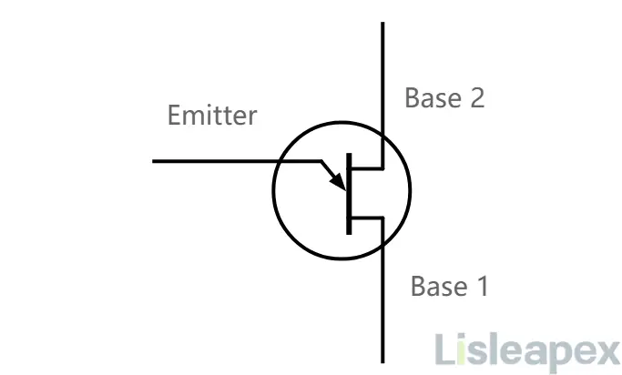
A Unijunction Transistor (UJT) is a semiconductor switching device with three terminals: emitter (E), Base 1 (B1), and Base 2 (B2). Unlike typical transistors, it contains only one pn-junction.
1. Construction
The UJT features a lightly-doped N-type silicon bar forming its main body, with an alloyed P-region near the middle, creating a single PN junction with the N-bar. This P-region connects to the emitter terminal (E), while the regions on either side form the Base 1 (B1) and Base 2 (B2) terminals.
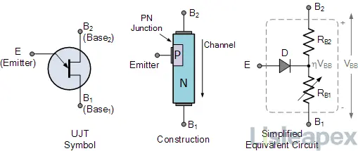
2. Working Principle
Under varying voltage conditions, the UJT exhibits changes in resistance between the emitter and base terminals. At specific thresholds, a sharp decrease in resistance occurs, leading to a significant increase in current flow from emitter to base. This behavior enables it to function as an electrically controlled switch rather than a linear amplifier.
3. Types
Original UJT: A simple device with an N-type semiconductor bar and diffused P-type material defining its intrinsic stand-off ratio. The 2N2646 model is a commonly used version.
Complementary UJT (CUJT): Comprises a P-type semiconductor bar with diffused N-type material, similar to the original UJT but with reversed polarities. The 2N6114 model exemplifies this type.
Programmable UJT (PUT): A multi-junction device resembling the thyristor, it requires two external resistors to set parameters like the intrinsic stand-off ratio. Models like 2N6027 and 2N6028 exhibit similar characteristics to conventional UJTs when properly configured.
4. Application
UJTs find utility in various applications, including:
- Free-running oscillators
- Synchronized or triggered oscillators
- Pulse generation circuits at low to moderate frequencies
- Triggering circuits for silicon controlled rectifiers (SCRs)
- Thyristor triggering circuits for AC current control
- Magnetic flux measurement using UJT relaxation oscillators, leveraging the Hall effect
- Used extensively in the 1960s and 1970s for hobbyist electronics circuits due to their simplicity in building oscillators and pulse generators with just one active device.
What is BJT?
The Bipolar Junction Transistor (BJT) is a semiconductor device featuring three terminals: emitter (E), base (B), and collector (C). It operates by utilizing both electrons and electron holes as charge carriers, hence the term "bipolar." BJTs are pivotal components in electronic circuits, serving as switches and amplifiers.
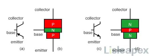
1. Structure
BJTs consist of three differently doped semiconductor regions: the emitter (p-type for PNP, n-type for NPN), base (n-type for PNP, p-type for NPN), and collector (p-type for PNP, n-type for NPN). These regions are connected to terminals E, B, and C respectively. The base, lightly doped and high-resistivity, lies between the emitter and collector. The collector surrounds the emitter, ensuring efficient electron collection.
2. Working Principle
Control of the current flowing from emitter to collector is achieved by regulating the current at the base terminal. A small current injected into the base controls a larger current flowing between emitter and collector. This characteristic enables amplification or switching functionality.
3. Types
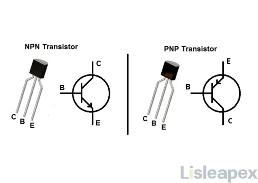
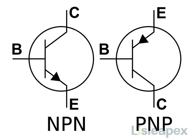
NPN Transistor: In this configuration, a thin layer of p-type semiconductor separates two n-type semiconductors.
PNP Transistor: Here, a thin layer of n-type semiconductor lies between two p-type semiconductors.
4. Application
- Amplifiers: BJTs serve as key components in electronic amplifiers due to their high transconductance and output resistance, especially in demanding analog circuits and high-frequency applications.
- Digital Logic: Emitter-Coupled Logic (ECL) utilizes BJTs in high-speed digital logic circuits.
- Temperature Sensors: BJTs can measure temperature by exploiting the temperature and current dependence of the forward-biased base–emitter junction voltage.
- Logarithmic Converters: The logarithmic relationship between base–emitter voltage and currents allows BJTs to compute logarithms and anti-logarithms.
- Avalanche Pulse Generators: BJTs with specific breakdown voltage characteristics can be used to generate sharp falling edges in pulse applications, such as avalanche pulse generators.
BJTs remain valuable in discrete circuit design, offering a wide selection of types and superior performance in certain applications compared to MOSFETs. They are often integrated with MOSFETs in BiCMOS processes to leverage the strengths of both transistor types.
Differences between UJT and BJT
|
Feature |
Unijunction Transistor (UJT) |
Bipolar Junction Transistor (BJT) |
|
Definition |
Three-terminal semiconductor switch with one PN junction, majority carriers control operation. |
Three-layer, two PN-junction semiconductor device, controls current flow. |
|
Terminals |
Emitter (E), Base 1 (B1), and Base 2 (B2), each with specific characteristics. |
Emitter (E), Base (B), and Collector (C), where B controls current. |
|
Circuit Symbol |
|
NPN: Arrow on emitter pointing outwards; PNP: Arrow on emitter pointing inwards |
|
Basic Structure |
Lightly-doped N-type silicon bar with alloyed P-region forms single PN junction. B1 and B2 are base terminals. |
Three semiconductor layers with emitter, base, and collector regions. Emitter-base junction controls current flow. |
|
Operation Principle |
Varying voltages change emitter-base resistance, triggering current surge. |
Base current control dictates emitter-collector current flow. |
|
Charge Carriers Involved |
Majority carriers (e.g., electrons) control current flow. |
Both majority and minority carriers (e.g., electrons and holes) involved in current modulation. |
|
Number of PN Junctions |
Single PN junction. |
Two PN junctions. |
|
Number of Semiconductor Layers |
Three layers. |
Three layers. |
|
Full Form |
Unijunction Transistor |
Bipolar Junction Transistor |
|
Applications |
Used in thyristor triggering, oscillators, and pulse generators. |
Amplifiers, switches, digital logic circuits, and temperature sensors. |
How to Choose between UJT and BJTs
To choose between a Unijunction Transistor (UJT) and Bipolar Junction Transistors (BJTs), consider the following:
For UJT:
- Suitable for switching applications due to current-controlled negative resistance behavior.
- Specific triggering characteristics based on emitter-base voltage.
- Simpler circuit design for relaxation oscillators and timing circuits.
- Handles smaller currents compared to BJTs.
- Commonly used in low to moderate frequency applications.
- May offer better temperature stability in some applications.
- Less common and more specialized, potentially impacting cost and availability.
- Less commonly integrated into integrated circuits (ICs).
For BJT:
- Can be used for switching and amplification purposes.
- Triggered by base current or voltage, offering more flexibility in circuit design.
- May require more complex biasing and circuitry, especially in amplifier configurations.
- Capable of handling larger currents, suitable for power applications.
- Operates at higher frequencies, suitable for RF applications.
- May require additional temperature compensation circuitry for stable operation.
- Widely available in various types and packages, often at lower costs.
- Commonly integrated into ICs, suitable for complex circuit designs.
Conclusion
UJTs and BJTs are two distinct types of transistors utilized as switching devices in electronic circuits. Despite their shared functionality, they exhibit significant differences in construction, function, device type, control mechanism, and applications.
The primary disparity between these devices lies in their structure and conduction mechanism. A UJT is a single-junction device that conducts solely via majority charge carriers, whereas a BJT is a dual-junction device where conduction involves both majority and minority charge carriers.
In summary, UJTs and BJTs differ markedly. UJTs are unipolar, voltage-controlled devices with a single junction, primarily employed as switches. Conversely, BJTs are bipolar, current-controlled devices featuring two junctions, capable of serving as both switches and amplifiers.
The choice between UJT and BJT depends largely on specific application requirements, whether for high-speed digital circuits or robust pulse generation circuits. Understanding these disparities aids in making informed decisions when selecting components for electronic projects.
FAQ
-
Which one is more commonly used, UJT or BJT?
BJT is more commonly used due to its versatility, wide range of applications, and ease of integration into electronic circuits. Its ability to amplify signals and switch high currents makes it a fundamental component in various electronic devices and systems. UJT, while useful in specific applications, is less commonly encountered in modern electronics.
-
How do UJT and BJT differ in terms of biasing and voltage/current relationships?
UJT requires a voltage trigger to reach its peak-point voltage (VP), where it exhibits negative resistance. Its emitter-to-B1 voltage (VBB) and emitter current (IE) are significant parameters for its operation. BJT, on the other hand, operates under different biasing conditions, such as common emitter, common base, and common collector configurations, with relationships between base current (IB), collector current (IC), and collector-to-emitter voltage (VCE).
-
How do UJT and BJT differ in structure?
A UJT has three terminals: emitter, base 1 (B1), and base 2 (B2). It consists of a single P-type semiconductor material with an N-type material lightly doped at one end. On the other hand, a BJT has three terminals: emitter, base, and collector. It consists of two P-N junctions and two layers of semiconductor material: P-type and N-type.
-
What is the difference between UJT and BJT?
UJT stands for UniJunction Transistor, while BJT stands for Bipolar Junction Transistor. Both are types of semiconductor devices used in electronic circuits, but they have different structures, characteristics, and applications.
Stay updated with Lisleapex by signing up for the newsletter